

SIPBS Design Specifications
The dsign specifications of the SIPBS building HVAC plants, systems and comfort levels are as described below.
Boilers
Three gas fired boilers, each with a capacity of 592 kW, operating on a lead/lag basis on a weekly interval provide low temperature hot water (LTHW). Water is supplied at flow temperature of 70°C to meet the heating requirements for the whole building.
They are controlled by a temperature sensor on the return section of the shunt circuit, rather than flow temperature to maintain a return temperature of 50°C. On successive weeks, each main gas boiler system will be the lead unit for the duration of that week. First lag selection changeover occurs each Sunday at midnight. On start-up only the lead gas boiler system is enabled but if the return temperature falls below the set point then the lag boiler will be enabled. The lag boiler system will run for a minimum of 5 minutes.
The BMS monitors the temperature in the flow and return from the boilers via an immersion temperature sensor.
Chillers
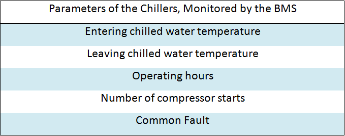
Cooling is provided by chilled water from chillers (647 kW capacity). These are enabled by the BMS upon registering a demand for chilled water from any of the locations provided with local cooling devices. Two chilled water pumps, on run / standby scheduling, pump chilled water. The BMS swaps the designated pump every week. Upon pump failure, auto changeover occurs. The BMS also monitors inlet and outlet temperatures of chilled water, operating hours, number of compressor starts and common faults.
Duct Mounted DX Coils
DX Coils are installed within the common supply ducts serving the Laser Labs and the Fermentation Labs complete with externally mounted condenser unit with interconnecting refrigerant pipe work. They function primarily for dehumidification when the central AHU CHW coils are unable to maintain desired humidity levels within the space. Humidity sensors are positioned to adequately reflect the return air room conditions. The DX coils are enabled when the return air humidity levels rise above 60%RH. This drops the humidity level to 50% RH +/- 10%. Any re-heat required is provided by either terminal re-heat duct mounted coils or Fan Coil Units.
Chilled Beams
Within the office areas and the write-up areas active chilled beams are installed and have integral radiant panels. These are sized to provide a source of heat to these spaces together with the raised supply air temperature being delivered to the beams. There are two different types of Chilled Beams installed within the SIPBS building;
- Ceiling Mounted
Active chilled beams with integral radiant panels are installed within the office areas and the write-up areas. These are sized to provide a source of heat to the spaces together with the raised supply air temperature being delivered to the beams. There are two different types of Chilled Beams installed within the SIPBS building;
Exposed Multi Service Chilled Beam
The multi service Chilled Beams are installed within the write-up areas on level 4, 5 and 6. They are, also, two beams butted together to make one continuous beam. The multi service beams also incorporate lighting as detailed on the E200 series. The chilled beams are controlled utilising 2-port control valves base on the following LTHW and CHW flow and return conditions;
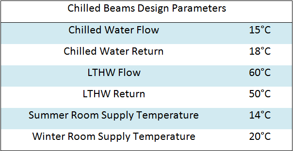
The chilled beams 2-port valves are controlled via a room temperature sensor and through the BMS. They also incorporate radiant panels that are capable of offsetting heat loss load together with the raised supply air temperature.
Cooling from the chilled beam is achieved by a combination of cool air from the nozzles and cooling coils on the chilled beam.
In each of these rooms the two valves and the room temperature sensor are provided as part of the BMS.
Under Floor Heating/Cooling
Under floor heating/cooling is provided to the level 1 entrance area and cafe. The system is fed from the LTHW and CHW circuit to the under floor manifold located in the level 1 clean cupboard. To prevent cracking of the slab a shut valve prevents any flow in excess of 50°C should the control valve fail. The control of the under floor heating is provided by the designer/installer.
Over Door and Warm Air Heaters
Over the disabled pass door within the entrance area beside the revolving door there is an overhead warm air heater.They are enabled in accordance with the selected time scheduling and in relation to the temperature in the entrance area. Over the disabled pass door within the entrance area beside the revolving door there is an overhead warm air heater.
Air Handling Unit
Air is delivered and circulated through the building by four air handlings units each having 2 2-port or 4-port valves that maintain a minimum air flow rate of approximately 50%. Each has a network of pipes through them from the LTHW and chilled water system.
AHU1 - North Primary and Secondary Labs
Air delivery to the north primary and secondary labs is from AHU1 (8.28 m3/s capacity), which conditions external air to ensure that set internal conditions within the Labs are maintained. The minimum supply air temperature is 13°C to the primary Labs. The secondary Labs have Fan Coil Units that are capable of maintaining the internal temperature of the room at the specified level. The primary labs have terminal re-heat coils that maintain the internal temperature at specified level. These supply and extract units are variable volume, depending on load and the number of safety cabinets & fume cupboards that are operational, to modulate the supply and extract air volumes. The fans modulate to maintain a constant pressure within the riser duct.
Humidifiers are installed within the supply ductwork to ensure a minimum humidity level for all microscope rooms of 50%RH +/- 10%.
AHU2 - South Primary and Secondary Labs
The south primary and secondary labs are fed air from AHU2 (10.66 m3/s capacity), which conditions external air and delivers at 13°C. The secondary labs have Fan Coil Units or terminal re-heat coils that maintain internal temperatures at a specified level. The primary labs have terminal re-heat
The units are variable volume similar to the north labs. VAV/motorised dampers are installed to modulate the supply and extract air volumes with the fans modulating to maintain a constant pressure within the riser duct.
Humidifiers are also installed within the supply ductwork to ensure a minimum humidity level for all microscope rooms of 50%RH +/- 10%.
AHU3 - North Primary and Secondary Labs
The north specialist labs are also fed air by AHU3 (3.30 m3/s capacity). It conditions external air and delivers at 13°C to provide cooling to the specialist Labs. There are fan coil units or duct mounted re-heat coils installed in the Labs that maintain internal temperatures at specified levels.
Humidifiers are installed within the supply ductwork to ensure a minimum humidity level for all microscope rooms of 50%RH +/- 10%.
The fermentation lab and the laser labs have terminal DX cooling coils installed on the common supply ductwork to reduce the humidity of the supply air when the central AHU’s cannot remove all the moisture in the supply air.
AHU4 - Office
Air is delivered to the offices and meeting rooms from AHU4 (6.83 m3/s capacity). This delivers conditioned air, drawn from the outside, at 14°C. Terminal chilled beams, fan coils or duct mounted coils ensure that internal conditions within the rooms are maintained.
Constant volume supply and extract units provide minimum fresh air to all rooms.
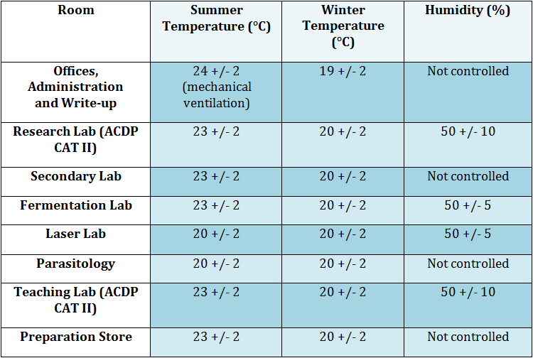
Design Comfort Parameters
The comfort parameters of the rooms supplied by the AHUs are shown below.
Run Around Coil Heat Recovery System
Heat recovery is achieved for all AHUs through a run-around heat recovery system designed to optimise energy use.
At the heart of this philosophy is the desire to recover the heat from the air which is being extracted from the atrium plus laboratories and to use it to temper fresh air that is supplied into the building.
The extent to which this can be achieved is influenced by the profile of the heat load in the building and the volume of air being transferred at any given time. To assist in this philosophy, preference is given to the use of heat from the heat recovery coils over that of the LTHW fed coils.
The circuit comprises one complete circulation system.
Control Philosophy
The circulation pump is enabled in line with the time schedule, by which time the extract AHUs will have started in accordance with their own control philosophy. Two or three port valves (as identified on the controls description), fitted to the supply of AHUs modulate to maintain an off coil temperature from the heat recovery coil as high as possible without exceeding the required supply air temperature from the relevant AHU.
By use of two port valves the benefit of a reduction in pump speed is achieved. When no heat is required by any of the supply AHUs, the pump on the run around coil system stops.
The pump set is of the variable speed type and operates to maintain a constant system pressure.
Fan Coil Units
Fan coil systems provided with an acoustically lined discharge plenum box with flexes and an externally insulated drain tray are installed in each of the various rooms.
All are arranged for draw through operation and fit washable/vacuum cleanable filters on air intakes. They have connections to the LTHW and CHW mains via copper tails with pulled bends to accommodate movement and expansion. Each diffuser plenum box and fan coil unit have at least one spare duct connection. Volume control dampers are fitted to each spigot of the fan coil discharge plenum and not at the diffuser plenum.
All fan coil unit control valves are two-port modulating local ball valve with integral strainer fitted on the flow pipe to each FCU, with an ultra low flow commissioning set on the return pipe work.
Fresh air, generally, is introduced into the rear of the fan coil units and then into the space through the fan coil unit supply ductwork and diffusers. In specialist labs where the ceiling void is pressurised the supply air is introduced differently. Return air temperature sensors are located to the back of each unit.
The air distribution pattern of the linear diffuser within the IT teaching room and the various meeting rooms ensures that full load heating and cooling capacities can be introduced into the space to provide a complete mixing system, without causing discomfort to occupants. The return air path to the fan coil is via the unused areas of the linear diffuser and via dedicated return air grilles/diffusers as required.
Each fan coil unit is fully addressable by the BMS.
Pipe work is run on each floor to serve FCU’s using flow and return through a four-port control valve. These provide control in response to a room temperature sensor for the relevant zone. The room temperature sensor has been provided as part of the BMS.
The fan coil units are all provided with a local BMS controller that is used to enable the unit in relation to the relevant time schedule and to control the four-port valve.
Duct Mounted Re-heat Coils
Terminal Re-heat Coils are installed within the common supply ducts serving the cafe, offices, meeting rooms and various Labs. The coils are for controlling individual room temperatures and re-heating after DX dehumidification purposes. Temperature sensors are positioned to adequately reflect the return air room conditions.
Fan Convectors (Control Connections)
The fan convectors are ceiling or wall mounted in selected areas. A two-port control valve is provided for each fan convector. This operates on an on/off basis in response to a return air sensor. It is controlled by the BMS in relation to the relevant time schedule and the room temperature.